


We have created a device that interprets the NTSC video signal from the video game Rock Band and outputs audio signals via a pair of speakers to simulate a human singer playing the vocalist part.
We chose to pursue this project since we were interested in doing a project related to music. We were inspired by the automated Rock Band guitarist from last year's ECE 4760 projects. People criticize Rock Band guitarists, saying that they should learn how to play a real guitar. Playing the vocal track on Rock Band requires actually being able to sing. We thought the idea of being able to emulate a human singing based solely on reading a few lines on the screen was pretty cool, so we decided to pursue this idea.
High Level Design
Ever since the release of Guitar Hero and online statistics comparing players based on their scores, people have been trying to gain an advantage by creating an automated player that would consistently achieve perfect scores. It wasn't until Rock Band was released that vocals as an instrument were introduced, and people were much less inclined to automate singing as everybody could hear your automated singer and would know you were cheating. However, just because the automated singer can't be used for improving your online statistics doesn't make it any less interesting. Ultimately, the goal is to automate the functional equivalent of a person humming along to a song, and anything related to copying what we can do inherently as humans is cool.
The basic premise is simple: sing a note (in the form of a sine wave of a specific frequency), determine how far off we are from singing the correct note, adjust the frequency of what we are singing, and repeat. Since Rock Band only requires that the note's pitch be correct, we can sing using sine waves rather than words! In order to accomplish this, we need to analyze the video signal to determine where we are singing (indicated by the white "puck" on the left side of the screen) and where we should be singing (looking ahead at the upcoming notes). Depending on the magnitude and sign of this positional difference, we can adjust our output signal's frequency accordingly, and repeat this to sing.
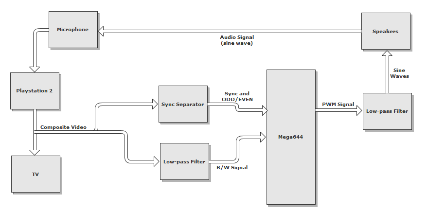
Taking the composite video signal from the Playstation 2, we pass this signal to the TV (so we can watch as we play) and to our circuit. The video signal is filtered to remove color and is passed into the analog comparator in the MCU, where it is compared against a threshold so we can determine when we are reading a line with a note present (a note on the black background will appear bright and exceed the comparator threshold). The video signal is also sent into a sync separator chip that generates the video reference signals we need to determine what line/frame we are reading at any given time.
Logical Overview
In order to analyze the video signal, we need to interpret the NTSC color standard in which the video is encoded. The NTSC standard consists of about 60 video frames per second (or 30 interlaced frames per second), with each frame containing 525 lines (486 of which are visible, 39 used for synchronization/retrace). This gives us an average line speed of (60 frames/second) * (525 lines/frame) = 31500 lines/second, or 32 us/line. Using a 20MHz clock, for a cycle time of 50ns, we have roughly 600 cycles per line for computation. Thus, this project is certainly achievable using the ATMega644.
Hardware
Since we are playing Rock Band on a Sony Playstation 2, we used the standard composite video output of the Playstation 2, which outputs video using the NTSC standard. In order to correctly analyze the video signal, we need to extract the sync signals (VSYNC and BURST) to keep track of when a new frame and line begins, respectively, as well as an odd/even bit, to determine which specific line we are reading since the video signal is interlaced.
Video Signal
The first step is to filter the video signal so that it is easier to analyze before passing it into the MCU. The NTSC video signal, transmitted over ~5.5Mhz, is encoded using luminance and chrominance (for brightness and color, respectively). The luminance is transmitted over the entire channel, while the chrominance is transmitted at ~3.5MHz. Since we are solely interested in the vocal signal (which appears as a green track on the black background), we do not need to differentiate between colors, but rather are only interested in detecting the presence of the vocal track at a certain position on the screen. This can be accomplished with just the luminance signal, which is essentially a black and white signal after the chrominance has been filtered out.

NTSC Video Encoding
This simplifies things greatly, as the luminance signal can be extracted by simply passing the video signal through a low-pass filter with a cutoff around 2MHz. Some high frequency detail is lost, but it is unnecessary for our task. Additionally, it would be very difficult to extract the chrominance, as the MCU would have to have its frequency synchronized with the carrier frequency as the chrominance is encoded using QAM (quadrature amplitude modulation).
We opted to use an active Sallen-Key low-pass filter as we wanted unity gain, and the gain dropoff from two poles at our cutoff frequency. It was necessary to find an op-amp with a high enough unity gain bandwidth to filter our signal. We found the LM837 in lab (low noise with 25MHz GBP) and decided to use it rather than ordering an expensive high speed video op-amp that would work equally well. To get rid of ripples in the power supply showing up in the filtered output, large decoupling capacitors (0.1uF) are placed between +5V/-5V and ground (not shown).
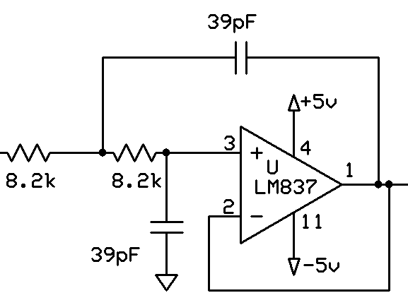
Video Low-pass Circuit
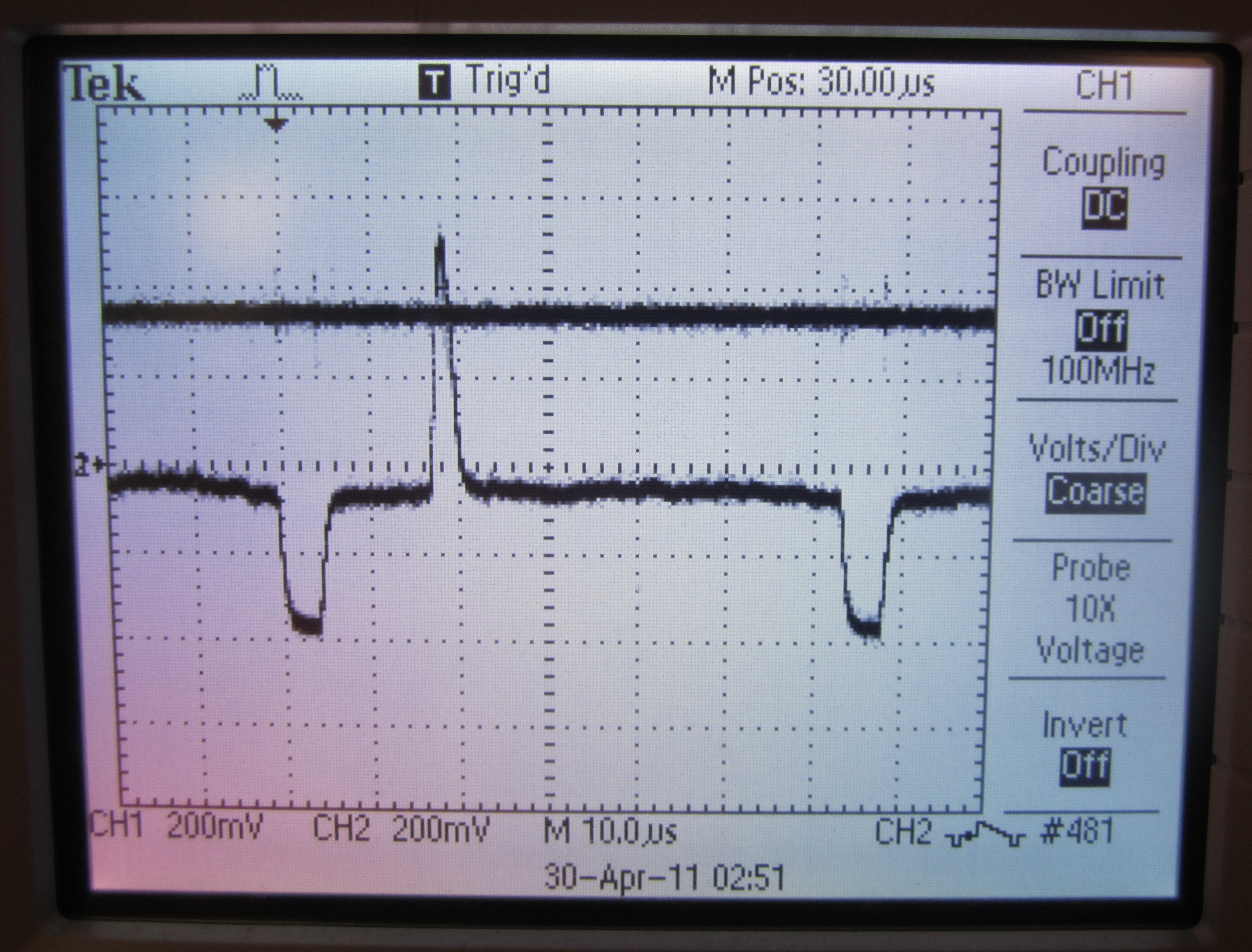
Below is the NTSC video signal, and the low-passed luminance signal. Much of the high frequency spikes are removed, making it much easier to analyze in the MCU.
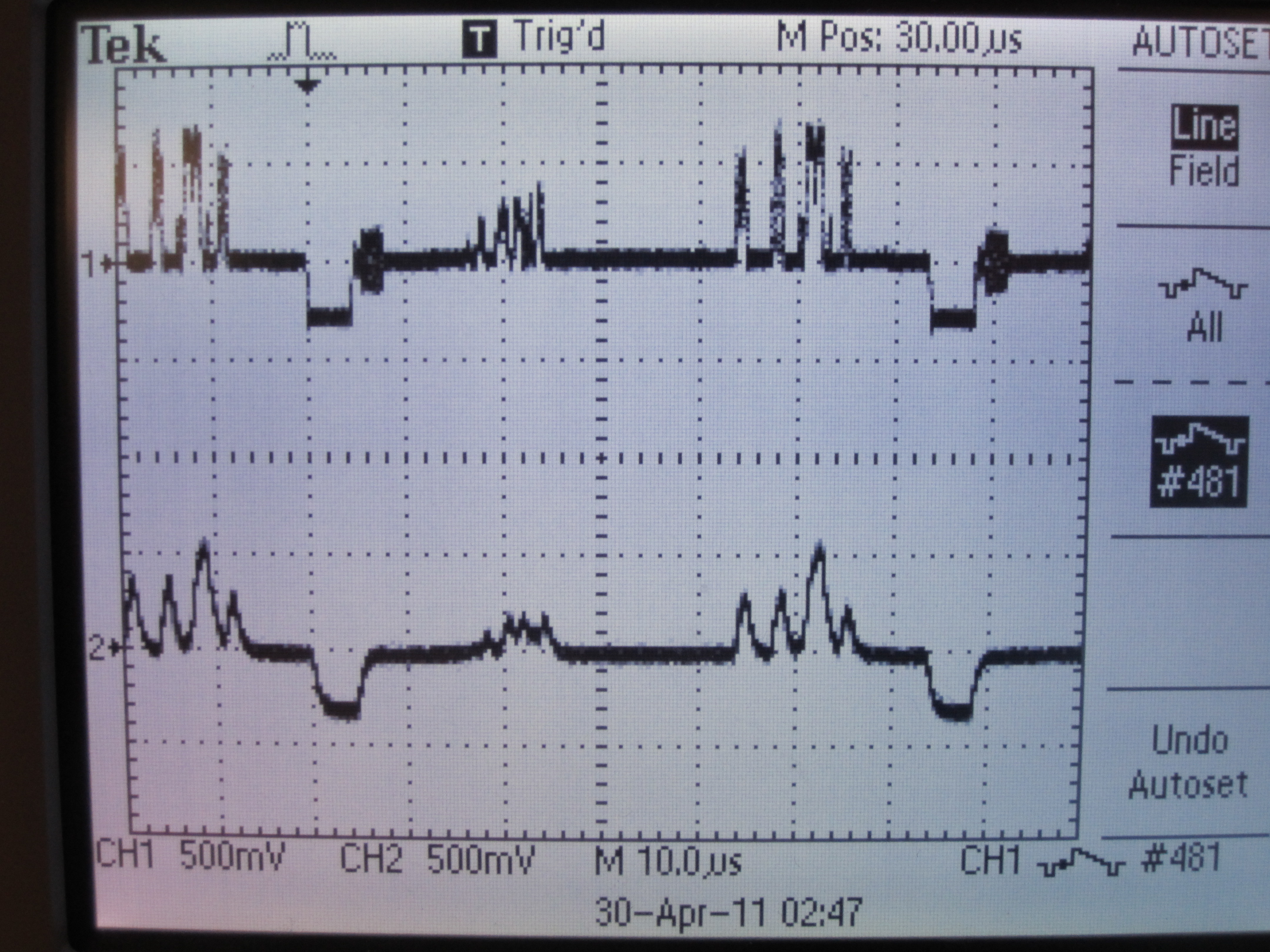
NTSC video signal (top) and low-passed version (bottom)
This video signal is fed into the positive end of the on-board analog comparator (PIN B.3).
Reference Signals
Now that we have a clean video signal feeding into the MCU, we need to analyze specific points on specific lines. To do this, we needed to extract the sync reference signals (VSYNC, for a new frame, and BURST, for a new line). We had initially intended to design this circuit ourselves (using a state machine and edge detection), but after taking a look at last year's Automated Rock Band Player project, we decided to use the same chip, the LM1881 Video Sync Separator. This chip takes the AC coupled composite video signal, and extracts the sync signals, as well as an odd/even signal, since the video signal is interlaced. These reference signals are sent to the MCU so we can determine the individual lines we are reading at any point in the video signal.
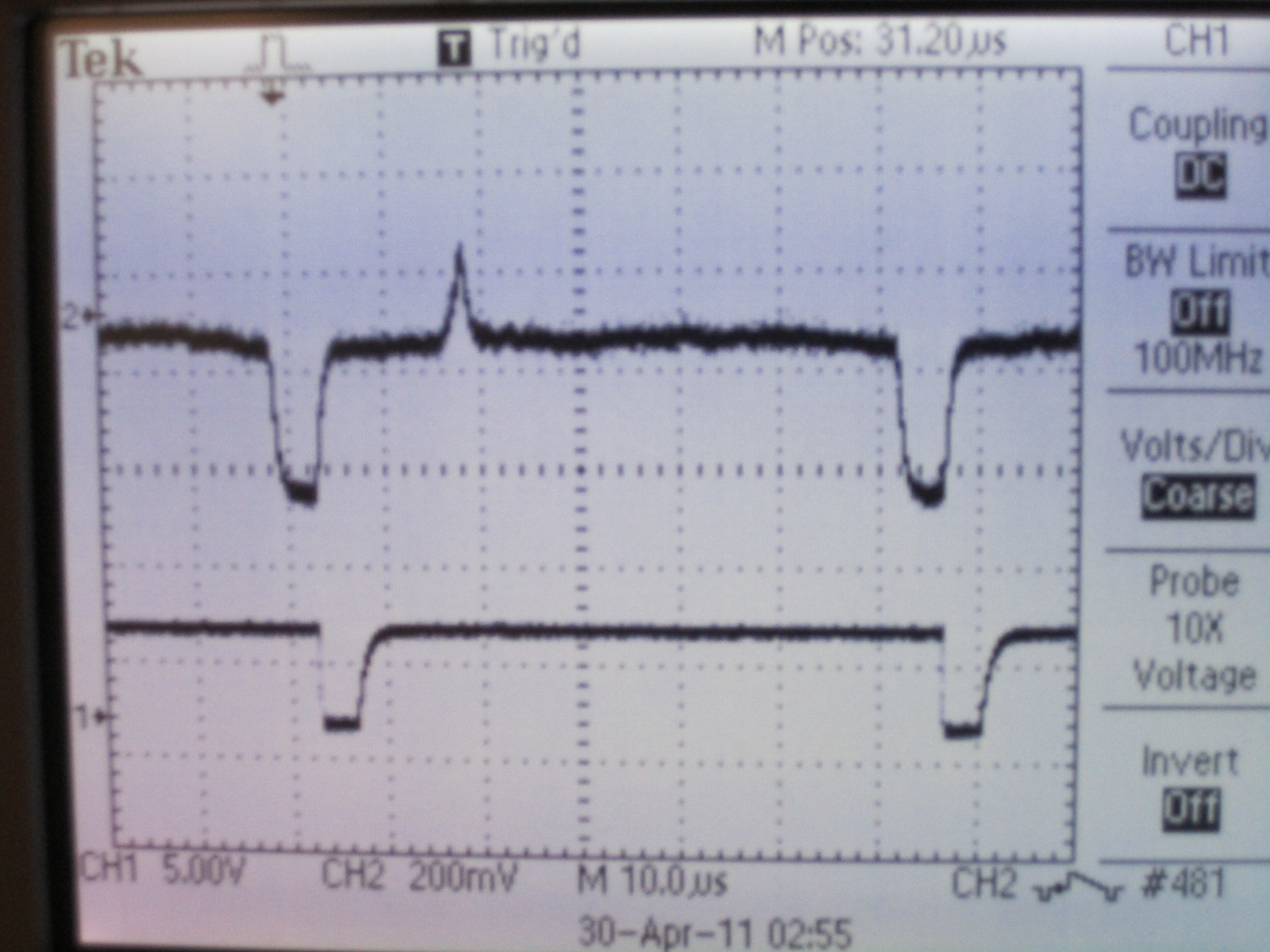
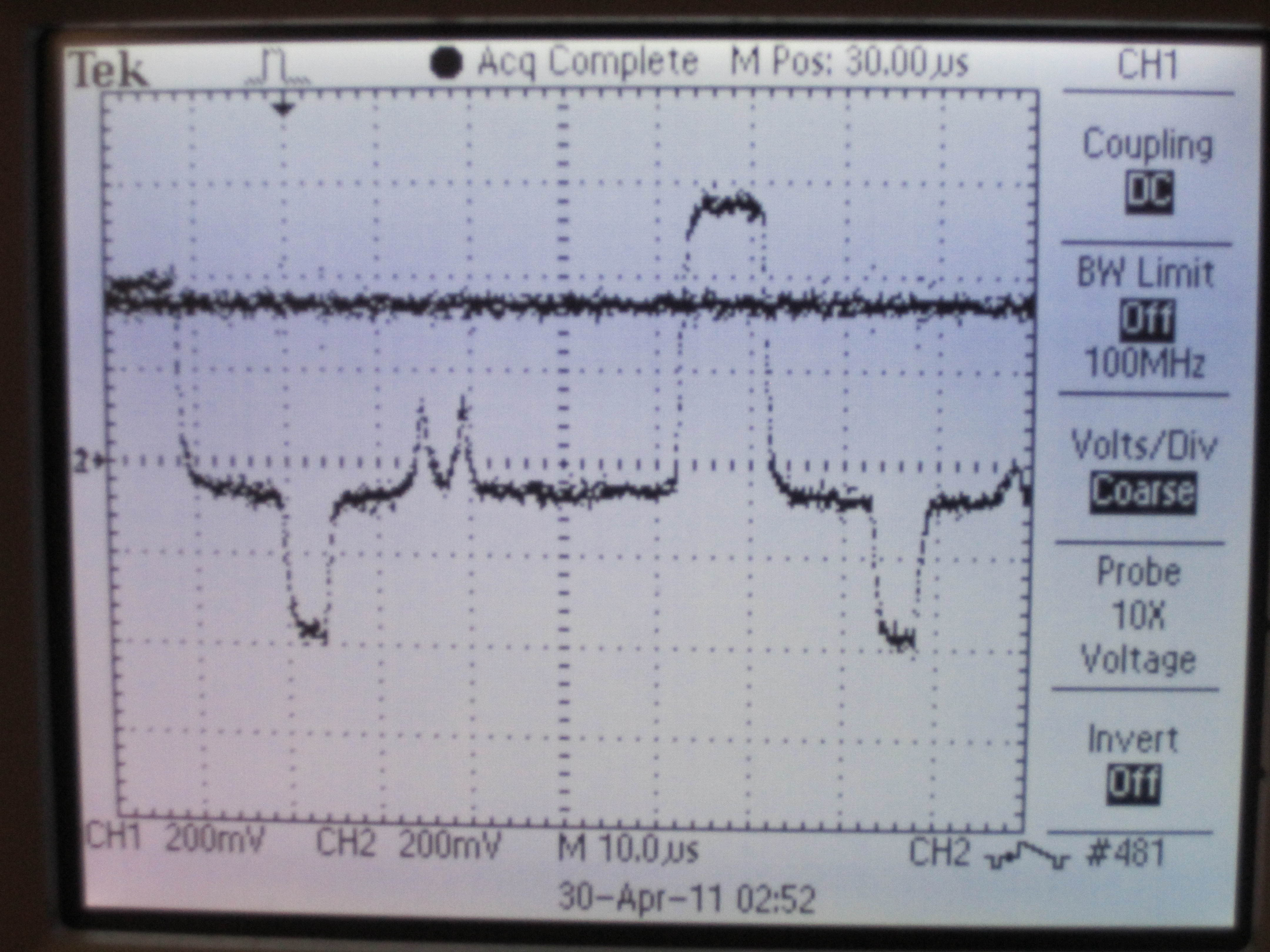
NTSC video signal (top) and HSYNC/BURST output from LM1881 Sync Separator (bottom)
Analog Comparator
Composite video varies its signal over the range of 0 to 1V, with ~0.3V corresponding to black, and ~1V corresponding to white. Thus, a bright signal (white, when the chroma is filtered out) will be at a much higher voltage than the black background signal, making it possible to use a voltage threshold and a comparator to check for the puck/notes.
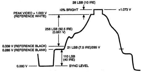
Composite Video Encoding
The low-passed video signal is fed into PIN B.3, or the positive terminal of the on-board analog comparator. A threshold voltage is fed into the negative terminal, PIN B.2, of the on-board analog comparator. When the video signal exceeds the threshold, the ACO register reads a "1", and otherwise, it reads a zero. With a clever use of software delays, we can check the brightness of an individual line at any point on that line to determine if that note should be sung.
For tuning purposes, the threshold is made using a resistive voltage divider and a potentiometer, with a large capacitor added to reduce noise from voltage source ripples. We found that the threshold works best when set to 362mV.
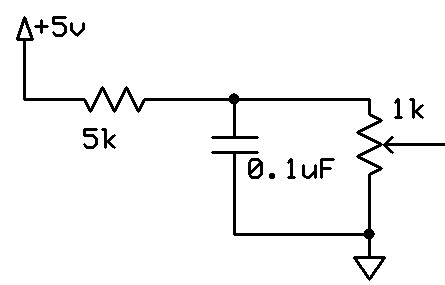
Comparator Threshold Circuit
One added complication is the need for a shared threshold for the singing "puck" and the notes to be sung. The threshold had to be chosen so that both could be detected, while still preventing any noise from wrongly triggering the comparator.
NTSC video line with "puck" spike and comparator threshold
NTSC video line with note spike and comparator threshold
Audio Output
Once we have analyzed the video signal and have determined what notes are to be sung, we generate an audio signal. Using the MCU's PWM mode, some filtering, and basic computer speakers, we generate continuous sinusoids of various frequencies (between 440Hz and 1000Hz, covering over an octave) that correspond to notes that are to be sung.
Software
We attempted to keep our software as simple as possible in order to minimize subtle bugs. After initializing, the main software components are the external interrupts to determine the location on screen, the timer0 overflow interrupt to generate the PWM signal, and the main control loop.
Initialization
During initialization, we are concerned primarily with two features: the audio output and the video handling. To set up the PWM for sound, we initialize a prescalar of 8 and interrupt on overflow for timer0. . We also enable fast PWM, outputting on pin B.4. We then populate an array to store the possible frequencies for outputting. Finally, we initialize a 256-element sine table, which stores the value of a 127-amplitude sine wave, indexed over one period.
The video initialization is slightly simpler. We initialize the interrupts for the BURST and VSYNC, with the appropriate edge triggers, all of which are described below. We also zero arrays which are intended to store the analog comparator results from the vertical lines containing the puck and the notes, as well as an array indicating which lines have already been computed on.
NTSC Signal and External Interrupts
We use an LM1881 chip to strip the sync signal from the NTSC signal, and use three of the outputs: BURST, VSYNC, and ODD/EVEN.
BURST Interrupt
The BURST signal is fed to external interrupt INT1. As mentioned above, this signal is triggered after every horizontal sync, indicating the start of a new line. We set the bits in EICRA register such that this is triggered on the falling edge of the signal. In this interrupt, we increment the global variable linecount by 2, telling us which line we are currently on. Note the increment by 2: this is because the signal is interlaced, meaning that each time the electron beam goes down the television screen, it visits every other line.
VSYNC Interrupt
The VSYNC signal is fed to external interrupt INT0. This interrupt is triggered on the rising edge of a VSYNC pulse rather than the falling edge, since we care when the new frame actually starts. This tells us that the electron beam is at the top of the screen. As such, we reset the linecount in this interrupt. However, due to interlacing, the first line will either be line 0 or line 1, depending on whether we are on an odd or even frame. We do a test on the ODD/EVEN signal to determine the reset value should be 0 or 1.
PWM DDS and Outputting Sound
In order to actually control the vocals, we output sound from a speaker, which feeds into the microphone and plays the game. We use the method of Direct Digital Synthesis (DDS), operated via PWM. This is the same procedure as used before in lab 2 for the DTMF dialer. During initialization, we computed the value of the sine function with magnitude 127 at 256 points over one period. We have an interrupt triggered when timer0 overflows. We increment an accumulator by some value, and use the high byte of this accumulator to index the sine table. Based on the value in the sine table, we set the relative times that PWM spends high or low. If we want a higher frequency output, we set increment higher. This causes us to travel through the sine table faster, resulting in a higher pitched sound.
In order to map frequencies to increments, we need an equation relating them. The relevant factors are the precision of the accumulator (2^32), the frequency of the clock (20000000 Hz), the number of ticks per increment (256), and the timer0 prescalar (8). Putting these together, we calculate the desired value of the increment to be inc = (2^32)*(256)*(8)*freq/(20000000) = 439804*freq. Based on our main control loop described below, we choose which frequency to output. We utilized 25 different frequencies, with increments stored in a table during initialization. The frequencies and corresponding increment values are as follows:
Frequency (Hz)Increment Value261.63 115066967
269.40 118486474
277.18 121905981
285.42 125529999
293.66 129154017
302.39 132995740
311.13 136837463
320.38 140905687
329.63 144973911
339.43 149284029
349.23 153594147
359.61 158159354
369.99 162724561
380.99 167564648
392.00 172404736
403.65 177528499
415.30 182652262
427.65 188083891
440.00 193515520
453.08 199268208
466.16 205020897
480.02 211116636
493.88 217212375
508.56 223670955
523.25 230129536
Analog Comparator and Main Control Loop
In the main control loop, we actually process the video signal and decide what frequency to output. There are two main sections of this main loop: gathering the data from the video signal and interpreting it.
Getting Data
In order to get the data from the video signal, we watch the lines that correspond to the vocal track in practice mode. Using the oscilloscope, we determined the line numbers that correspond to the vocal track are lines 400 through 450. When we are on the appropriate line, there are two things we want to check for the presence of: the "puck" (the arrow that indicates what frequency the vocalist is singing at), and the note that the vocalist is supposed to sing. Since these are at different vertical positions, we check these columns using specific delays. We have an if statement, checking if the current line is in the vocal chart and we have not yet checked for this line during this frame. If so, we delay by 11 µs, which we determined to be the position of the puck, relative to the horizontal sync burst. We then get the value from the analog comparator. As described in the hardware section, we have the AC compare the value from the video signal to some reference voltage which we have set. If the video signal is higher than the reference voltage, we take this to mean that part of the puck is at this location. We save this boolean result in an array. After this, we delay another 4 µs, which corresponds to the location which we are trying to set our output frequency to match. Again, we check the AC value and store this in a separate array. After we are done going through all the lines, we will have two boolean arrays, which should have 1's corresponding to where the puck is and where the notes are.
Interpreting Data
Once we have information on the puck and the note, we have to make decisions based on it. We do this once per frame, just after the last line of the vocal track. From the boolean arrays, we must determine where the puck and the note are. We find the median index of the 1 valued indices in these arrays, in order to estimate the location of the middle of the puck and the middle of the note. If the puck is above the note, we decrease the frequency, and vice versa.
In order to avoid the notes going too high or low, and ensure that the notes are evenly spaced, we discretize our frequencies. During our initialization, we computed several different increments and stored them in an array. We keep a variable to index this array. If we find that the puck is above the notes, we switch to the next, lower index. If the puck is below the notes, we increment the index to play a higher note. If the puck is within a two-sided tolerance of 3 lines of the note, we keep the index as it is. On certain songs, we find that a tolerance of 2 lines performs much better, so we use this tolerance instead. Based on this logic, we have a feedback loop, in which the frequency we output is adjusted to match the note.
Results
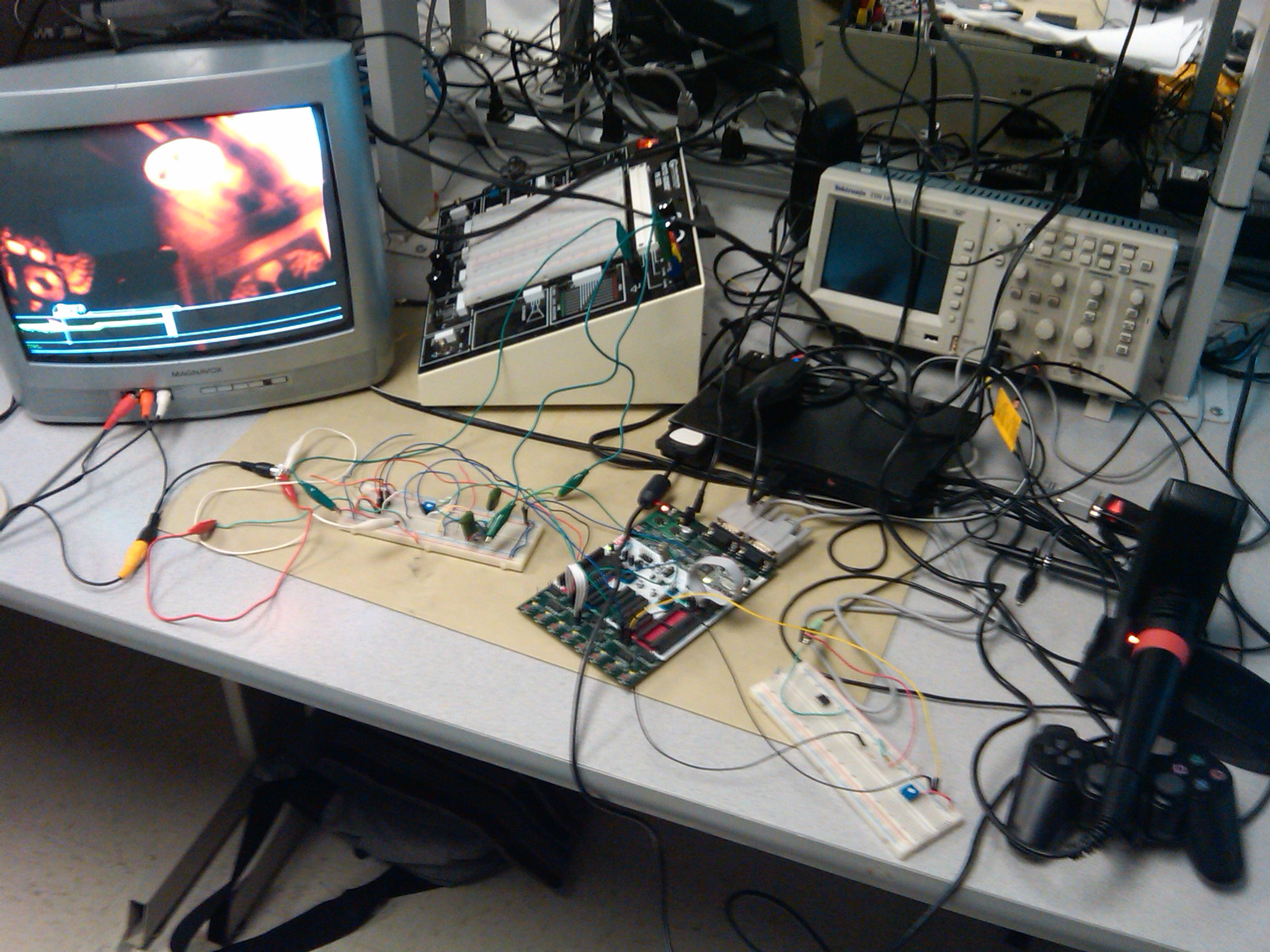
The messy result
We met all of the goals set forth in our project proposal. We were able to interface with the video signal, our microcontroller was fast enough to process the video/do the necessary calculations, and we output an audio signal of a relatively correct frequency.
Song (on expert)Messy (%)Weak (%)Okay (%)Strong (%)Awesome (%)Tom Sawyer 16 7 16 13 48
Enter Sandman 15 13 18 10 44
Foreplay/Long Time 8 25 25 19 23
Maps 27 27 15 4 27
Creep 16 22 24 14 24
When You Were Young 12 27 32 9 21
We found that our vocalist worked best on the more difficult songs that had many long, sustained notes with small changes in frequency. Many of the easier songs have large frequency jumps in lieu of long, sustained notes, and our vocalist performs less well (but still well!) on these songs. We also found it interesting that the accuracy changed by a couple percentage points after each run. We determined that this was mostly due to outside noise (people talking in lab, for example) that would bleed into our microphone input.
We ended up using training mode for our project, as the background video in the normal playing mode bled into the background of the vocal track giving us false triggers and much lower accuracy during the more "exciting" parts of the song. Training mode also removes the star power section, which turns the entire vocal track yellow and gave us many more falsely triggered notes.
We wanted to make our vocalist as easy to use as possible, so we limited the complexity of user interface essentially to just controlling the output volume. No more complexity is required as the vocalist automates the singing process, and all the user needs to do is stand in awe and watch.
Below are videos showcasing our final project:
Conclusions
Meeting Expectations
As previously mentioned, we accomplished all goals we set forth in our project proposal.
Interface with the video signal so that we can extract the sync and color signals
Extract part of a single column of pixels, so we can see the vocal player's instructions
Be able to process the instructions, so that we can see the position of the line which the player is to sing to
Generate a PWM signal and output to a speaker placed next to the microphone to match the pitch displayed on screen
Overall, we were very satisfied with our automated Rock Band vocalist. We never set an accuracy expectation, as we could potentially achieve 100% "Awesome" notes, but a more reasonable expectation is to have a majority of the notes in the top three categories (Awesome, Strong, Okay) and minimize the number of notes in the bottom two categories (Messy, Weak). We consider this to be a more reasonable goal to achieve as a "Messy" or "Weak" rating indicates we missed many of the notes or sung them very sloppily, while any of the higher ratings means we hit almost every note and sung them relatively well/slightly off key.
We had also decided that we wanted to focus solely on the singing aspect of the vocals, skipping the "percussion" sections that show up in some of the songs. It would be very hard to detect the percussion sections and even harder to have our device trigger it (as it requires a large change in volume rather than playing a specific frequency or making a large change to the output signal's frequency. Given that the percussion section does not even show up in every song, we deemed it not worth the time and effort that could be spent tweaking the vocalist to sing the parts that make up the majority of every song. As a result, songs with percussion sections will inherently lower our accuracy, as the entire bar of percussion is considered "Messy".
After getting the basis of our project complete and tweaking various parameters (the puck/note difference switching threshold, size of frequency jumps depending on the magnitude of the puck/note difference, how often we update the frequency), we realized our vocalist performed much better on songs that had fewer large note jumps (say from the top to the bottom the screen) and had little notes on the very edges of the screen (as the notes and puck were hard to read when they were close to overlapping with the singing boundaries), while it performed very well on songs with long sustained notes and smaller frequency drops. Thus, we decided to tweak our parameters to make the vocalist work very well at longer sustained notes, sacrificing some ability to make fast and accurate large note jumps.
Project Standards
The only standard relevant to our project is the NTSC video standard that the Playstation 2 uses to output video. We used the LM1881 Sync Separator to extract the SYNC and ODD/EVEN signals, and did not modify the video signal in the final iteration of our vocalist so we do not have to conform to the NTSC standard. Since we did not modify the PS2 microphone (and simply stick it up next to the speakers), we do not have to worry about conforming to any of Sony's device standards.
Intellectual Property
Our project idea and some design decisions were influenced by a previous year's project (Automated Rock Band Guitarist), which itself was influenced by autoguitarhero.com.
Ethical and Legal Considerations
Sony's Playstation Network (the online component of the game) does not allow cheating. Since we are essentially automating part of the game, Sony considers this cheating and thus we are not allowed to use our project on Playstation's online network. It would also be unethical to use online as you would be falsely representing yourself and your skill.
Our project was designed and constructed while adhering to the IEEE code of ethics. As our project is completely automated (save for setup and enabling/disabling), there are no safety or heath concerns as there is little human-device iteration. In fact, our project offers less risk than playing the game yourself! For identical reasons, our device does not discriminate by race, religion, or gender. We have not violated any laws or legal regulations in designing, constructing, or playing with our vocalist.
To the best of our knowledge, all claims made within this report are an honest representation of our work. We chose a project that we deemed doable for our combined technical skill level, and asked for assistance when that skill level was exceeded. We researched as much as we could before undertaking in this task, and tried to learn as much as possible before, during, and even after our project was completed.
Appendices
A. Source Code
Source files
vocals.c (6KB) – code containing ISRs, initialization, and main program logic, including video reading, processing, and sound generation
uart.c (5KB) – uart code from Bruce Land
Header files
uart.h (1KB) – exposes necessary UART functions
Download all files: code.zip (5KB)
B. Schematics
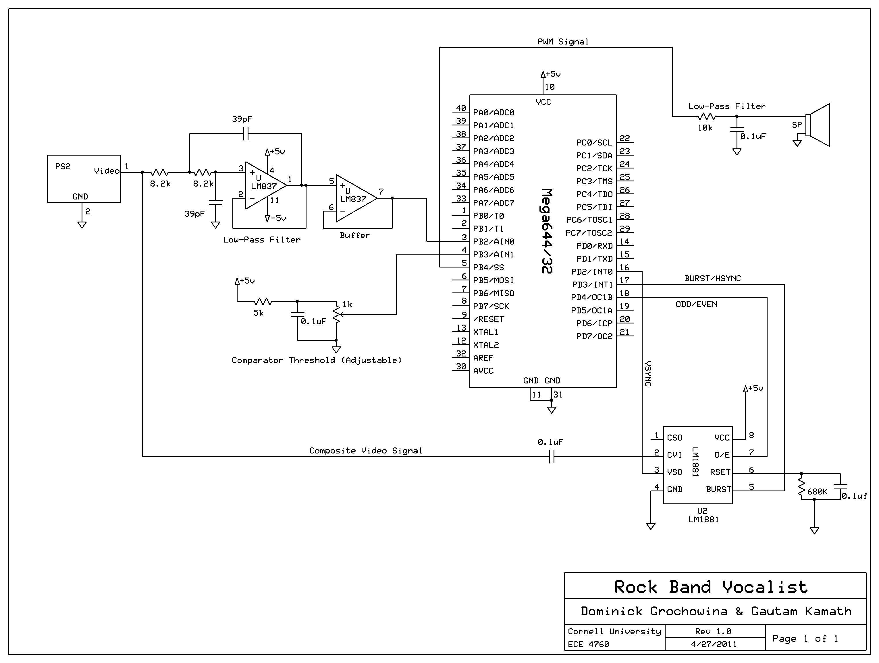
Hardware schematic [full-size image]. Download schematic file: vocalbot.sch (36KB).
C. Parts List
PartSourceUnit PriceQuantityTotal PriceSTK500 lab $15.00 1 $15.00
Mega644 lab $8.00 1 $8.00
Color TV lab $10.00 1 $10.00
Speakers lab $0.00 1 $0.00
white board lab $6.00 2 $12.00
LM1881 Sync Stripper DigiKey $3.11 1 $3.11
RCA Splitter Female to Male Amazon $2.99 1 $2.99
2 RCA Male/ 2 RCA Female Extension Amazon $7.53 1 $7.53
PS2 + accessories previously owned $0.00 1 $0.00
Rock Band Game previously owned $0.00 1 $0.00
LM837N lab $0.00 1 $0.00
10K Potentiometer lab $0.00 1 $0.00
1K Potentiometer lab $0.00 1 $0.00
External Power Supply (Proto-board PB503) lab $5.00 1 $5.00
0.1 uF capacitor lab $0.00 3 $0.00
0.47 uF capacitor/td> lab $0.00 2 $0.00
39 pF capacitor lab $0.00 2 $0.00
10k Ohm Resistor lab $0.00 1 $0.00
8.2k Ohm Resistor lab $0.00 2 $0.00
5.1k Ohm Resistor lab $0.00 1 $0.00
680k Ohm Resistor lab $0.00 1 $0.00
Wires + alligator clips lab $0.00 several $0.00
Total $63.63
D. Tasks
Gautam
Frequency-increment correspondence
Rock Band mechanics research
Musical tuning
Dominick
Hardware design
Filtering research and design
Everything else was done together. In particular, we used the pair-programming methodology when writing the software, in that we were both present and took turns programming. As a result, we ran into few software issues. All wiring, testing, and tweaking was done together as well.
References
This section provides links to external reference documents, code, and websites used throughout the project.
Datasheets
ATmega644PA (8-bit MCU)
LM1881 (Sync Stripper)
LM837N (Low Noise Quad Op Amp)
3386 (Trimpot)
Reference Code
Automated Rock Band Player by Jeff Yates and Li Yau
Vendor Sites
DigiKey
ExpressPCB
Background Info
NTSC format
Composite Video
Composite Video Separation Techniques
Stanford "TV Paint" lab handout
Another Automatic Guitar Hero player
Acknowledgements
We would like to thank Bruce Land and the lab TAs for running such an awesome class and helping us when we were stuck. In particular, we'd like to thank Jeff Yates and Tom Gowing for giving us advice, as they ran into several of the same issues as we did when they were working on their Rock Band Guitar player.
We would also like to thank everyone in the lab for being so patient and putting up with our annoying sounds at all hours of the day.
We would like to thank Kerran Flanagan and Adam Papamarcos for the website template which we adapted.
Finally, we would like to thank Amazon for the one-day shipping option.


No comments:
Post a Comment