


he DJ Touch is a portable turntable touchscreen and interactive LED display.
Our end goal was to produce a low cost touchscreen device, and demonstrate its application in a common consumer application. Out of an interest in electronic music, and with the knowledge of deejaying's close roots to electronics, we decided to develop a touch screen turntable.
The device relies on the concept of frustrated total internal reflection (FTIR) to detect user motion on an acrylic surface. Using a camera system and infrared LED setup, these blobs of infrared light are read into the microprocessor and detected using a dynamic thresholding algorithm. The data is streamed over serial using the FT232R USB connection and a compatible program on the user interface emulates the turntable motion. We have also written up additional code that uses the blob tracking for simple mouse movement. Using MATLAB's powerful image processing library, more complex interactions can be coded.
Touchscreen & LED Display
High Level Design
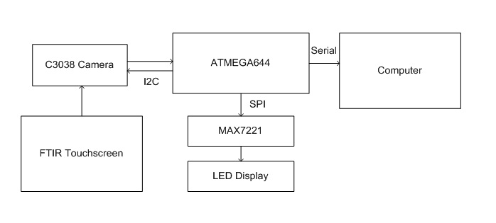
High level diagram of DJ Touch system
There has been a plethora of touchscreen gadgets in today's market of consumer electronic goods. Smart phones and portable entertainment devices are expected to ship with some form of touch screen functionality. In particular, several multitouch projects have been successfully completed leveraging on the FTIR effect. These include and have served as an inspiration for our build. DJTouch demonstrates the ability to build an interactive display using minimal processing resources for low cost.
At the heart of the device is an ATMEGA644 which is connected to a CMOS camera and a LED driver. With only a RS232 serial port to communicate data to the computer, we had to push most of the image processing to the ATMEGA644, outputting only a stream of bits representing the background/foreground data of the screen. The LED display allows the user to confirm that the touch screen is functional, if the computer is not used.
On the computer end, there is a serial read-in code that translates the binary bits of information into a full image. Applications can be developed to use the data to track motion across the screen, or as demonstrated in the main DJ application.
The system relies on the program Virtual DJ Home, which simulates a DJ deck. Configuring the appropriate keyboard inputs to the turntable actions, the user's rotational motion across the surface of the acrylic is translated into rotations of the turntable. This allows the user to "scratch" music. There is also an additional play/pause button, located in the center of the touch screen.
The project relies on I2C, SPI and serial communication protocols. I2C is used to program the camera to allow for optimal image capture of the touchscreen. SPI is used to drive the LED display, controlling up to a maximum of 64 LEDs using only four input wires from the microcontroller. The serial communication data stream is custom formatted in order to minimize the time needed to send data over the connection.
With the limited bandwidth of the serial port connection, our device speed is limited. With the addition of processing from the MATLAB front end, the low sampling rate can be compensated for, applying correlation to determine user movement. Using a reduced version of the code, which only outputs rotational speed, we can speed up the rate of image sampling and increase the sensitivity of the device. For demonstration purposes, however, we felt that streaming the full image was essential to show the proper operation of the touchscreen.
As the device's sole output is through the serial port connection, there were no applicable standards by which our device had to conform.
To our knowledge, while the term "multitouch" is patented by Apple, the concept of FTIR to track user finger presses across a surface predates the patent application.
Hardware
Our device consists of a touchscreen and a LED display. As a significant part of the project required setting up the FTIR touchscreen, we have documented the process of obtaining blobs on the acrylic surface. In addition, we will discuss hardware concerns regarding the LED matrix build and the physical camera characteristics.
FTIR Screen
Frustrated Total Internal Reflection is a multi-touch methodology developed by Jeff Han (Multi-Touch Interaction Research, 2006). Light directed from a material of a smaller refractive index to a material with a higher refractive index at an angle above that of a critical sum will be reflected totally. Light from the infrared LEDs directed into the acrylic is trapped in the material. When the user presses on the surface, the refractivity of the user's finger frustrates the light rays, breaking the TIR effect. This is visible as bright blobs on the camera.
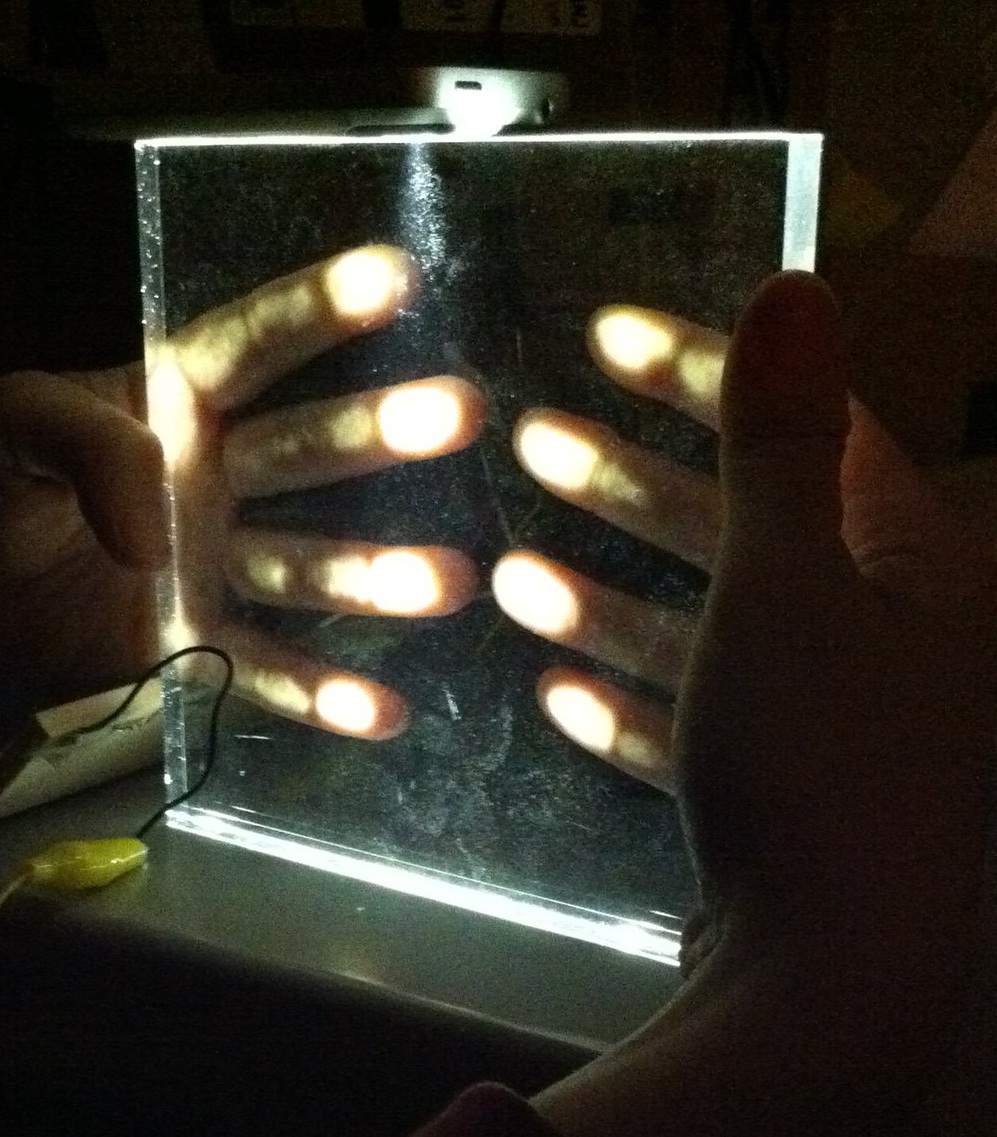
FTIR effect using visible light
The choice of acrylic was paramount for the application. We began with a piece of acrylic that was of insufficient thickness. In addition, we had manually machined the parts, leaving the edges unclear. After determining that the minimum thickness for the TIR effect was 3/8", we ordered a custom 1" 6"x6" acrylic that was polished. The acrylic can be tested with visible light. The amount of pressure needed to get the FTIR to be visible depends on state of the user's fingers. We noted that wet/oily fingers helped the effect. Future work might consider using a compliant coating of silicon, so that this issue is resolved.
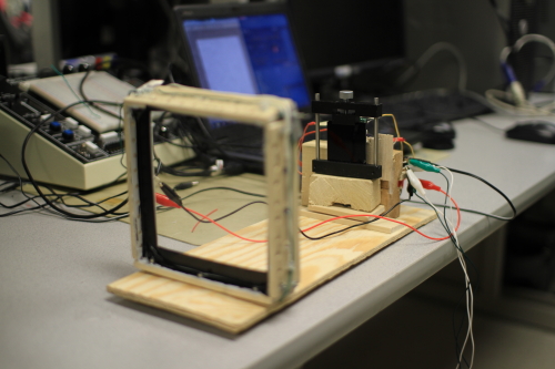
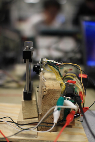
Touchscreen Setup
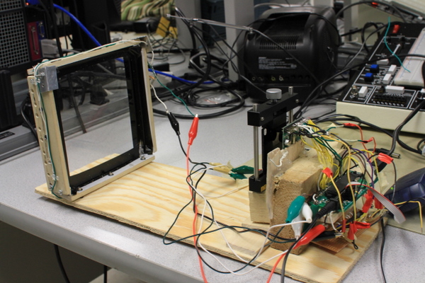
To maximize the effect, we painted the interior of the frame with white paint. This surface is highly reflective and allows the light to be reflected back into the acrylic material. We also taped the sides of the material to block out light shining directly from the LEDs. The device is constructed on a plywood base, fixing the distance between the screen and the camera. We intended to construct this to be a vertical box, for a more intuitive touchscreen surface. However, as the minimum distance between screen and camera is about 8", the structure would be more stable in a horizontal position.
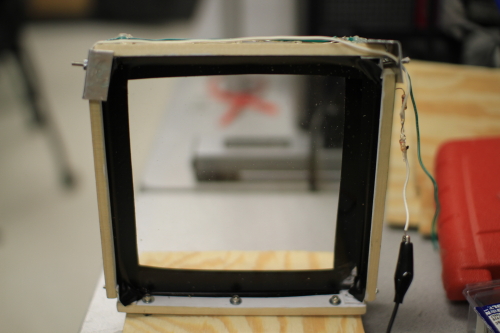
Close up of acrylic frame and LEDs
CMOS Camera
The CMOS camera is directed at the touchscreen, such that the field of vision includes the entirety of the 6"x6" screen. The screen is built from a piece of 1" thick clear acrylic with a frame embedded with 9 infrared LEDs. The LEDs output at a peak frequency of 940nm and have a radiant intensity of at least 25mW/Sr. This is the minimum intensity recommended for the FTIR effect to be observed. We began with small cheap LEDs with only 15mW/Sr, but could not observe the FTIR effect. Debugging this effect was troublesome because although most camera phone cameras can view infrared (as purple light), the FTIR blobs are not bright enough to be visible on them.
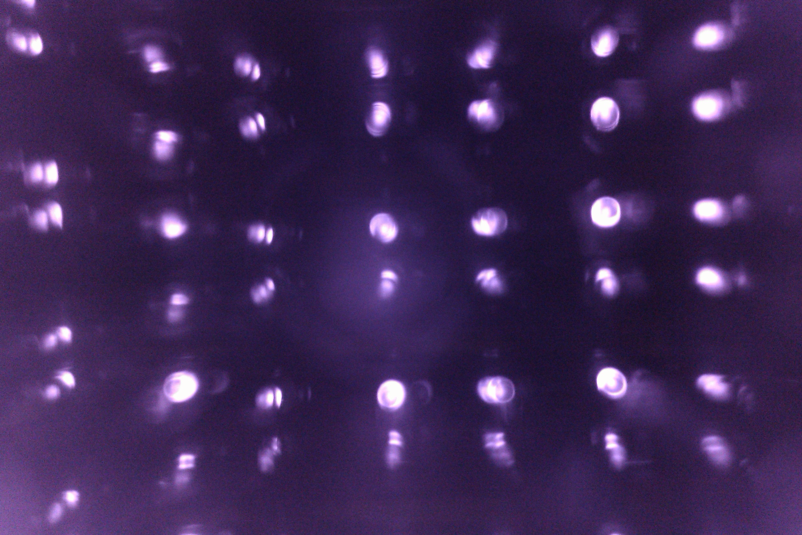
Looking into the acrylic frame
While we originally began with an ordinary webcam, modified to view IR wavelengths, we were unable to interface the Atmega644 with the device. We purchased the C3038 CMOS camera, which has been a popular choice in previous ECE4760 projects (Customizable Virtual Keyboard, Scanalicious) and has extensive documentation on its use. We made careful note to purchase the model that does not include the IR-cut filter. Consumer cameras often include a visible light filter that rejects infrared wavelengths, but often the image sensor on it is sensitive to the infrared spectrum. In addition, the camera in monochrome mode is sensitive to the desired wavelength of light for our application, or 940nm. The camera can be additionally programmed using I2C communication. The customization allowed us to maximize the camera's sensitivity to IR. Further details on the data capture of the image stream are given in the Software section of this report.
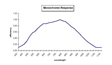
Camera Response
When developing the screen, we realized that the camera was very sensitive to ambient light. Since we relied on a monochrome image, the camera would be fooled by external sources of light. Thus, we sought out an infrared filter. After reading some IR photography enthusiast websites, we attempted to use the magnetic disc of a floppy disc as a filter. It also had the additional benefit of being a neutral density filter, helping to compensate for the long exposure time our camera had due to the slowed pixel clock. The disadvantage was that the floppy material was not a true IR filter, and its response to IR wavelengths with the filter attached was not sensitive enough to view the FTIR blobs. We borrowed a filter from Professor Pollock that allows light of wavelengths above 790nm to pass through. Using this filter, the system is insensitive to surrounding light in the environment. We did not test the system outdoors, where IR from the sun could impact the system. Given the proposed use as a DJ scratchpad, the device will most often be used in an indoor setting, or outdoors at night.
IR Filter
In testing out the FTIR effect, we had to adjust camera parameters until we could distinguish blobs clearly. The effect is strong, and the peaks where a finger is pressed against the acrylic can be seen. Another thing we noted was that when a finger was pressed, the average intensity of the screen increased. Thus we could not rely on a preset intensity threshold to distinguish the blobs from the background. In addition, we noted that light escaping from the frame edges was of a similar intensity to the FTIR blobs. Taping up the frame edges resolved the issue.
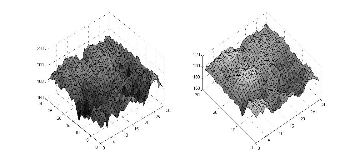
Comparison of background intensity levels and FTIR effect
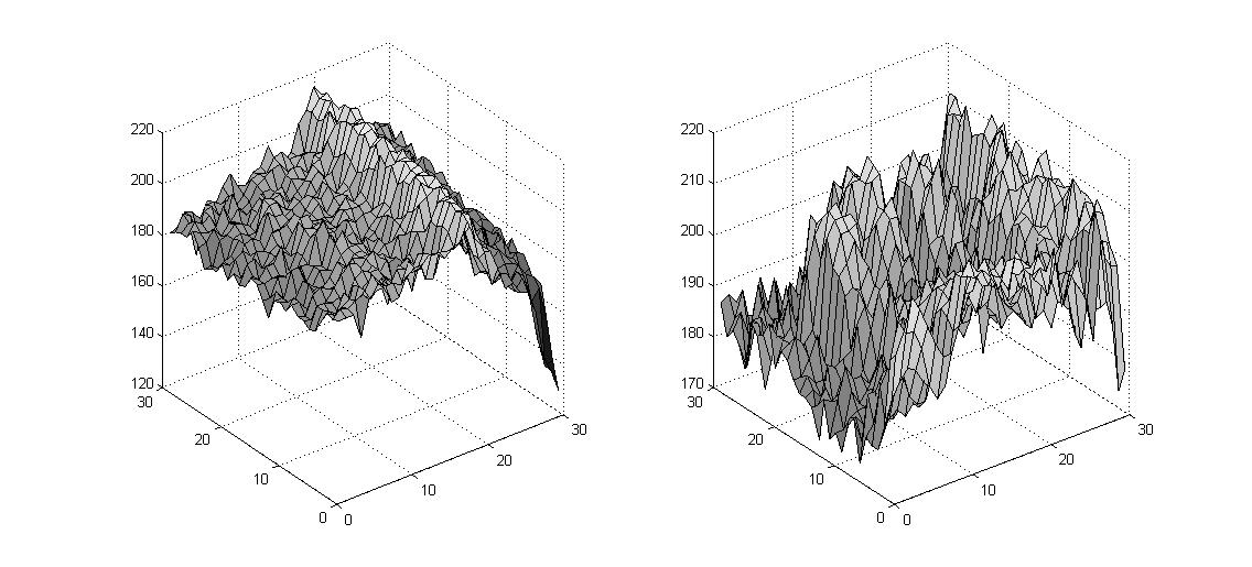
Infrared noise from embedded LEDs in the frame interferes with FTIR blob detection
We also utilized two CD4516BE counters to slow down the HREF and PCLK signals from the camera. We downsampled these signals by a factor of four. The camera runs at 3.3V, and we stepped down the 5V supply of the microcontroller board to run the camera. In addition, the I2C communication wires SCL and SDA each required a 4.7k pull-up resistor to 3.3V. While we originally used the internal pull-up registers on the Atmega644, we found that the output signals had a slow rise and fall time, producing a distorted digital signal.
LED Matrix
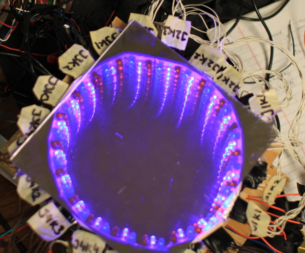
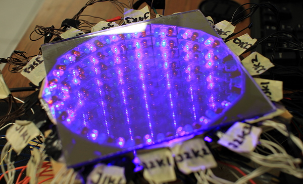
Top view of the tunnel
Our idea was to have a display to give the user an idea of how the virtual turntable was being scratched. We decided to use an LED driver, MAX7219, to control 60 LEDs arranged in a circular fashion. The LEDs are assigned to angles, and programmed to light up whenever the user activates the angles, by placing a finger in a predetermined zone.
The LEDs are wired in a matrix fashion, following the guide available at . There was significant bookkeeping involved to label the LEDs as they were placed in a circular fashion. Instead of handling individual LEDs, we grouped them into threes and used a pin holder to keep the wires in check when building the circuit.
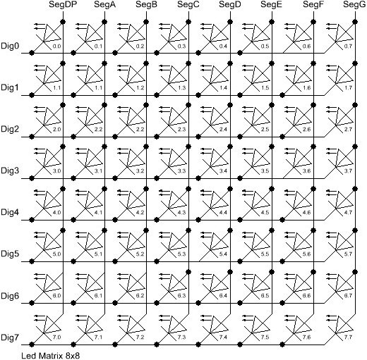
Wiring Schematic for the LED Matrix (source)
The circuit draws a maximum of 400mA, which occurs when 8 LEDs are lit up in a row. The MAX7219 utilizes the SPI protocol to communicate with the microprocessor. We originally started out with PDIP packaged MAX7219, but unfortunately blew our samples out after a trial runs of the matrix. Future users might consider the MAX7221 instead as it offers protection from electromagnetic interference and supports full SPI protocol.
The circular matrix is sandwiched between a mirror and an acrylic two-way mirror. When turned on, this gives an "infinity tunnel" of lights. Light from the LEDs is reflected between the mirrored surfaces. However, the two-way mirror allows some light to pass through, giving rise to the appearance of an endless stream of lights extending behind the surface.
We initially constructed the circuit on a breadboard, but had major issues with loose connections. We swapped over to a prototype board and it saved us the trouble of wires coming loose (non trivial, given the 120 wires in total). We intended to make pin holders to help keep the LEDs in place, but found that the connection between the LED pins and the holders were not consistent. Ultimately, we soldered all the LEDs in place.
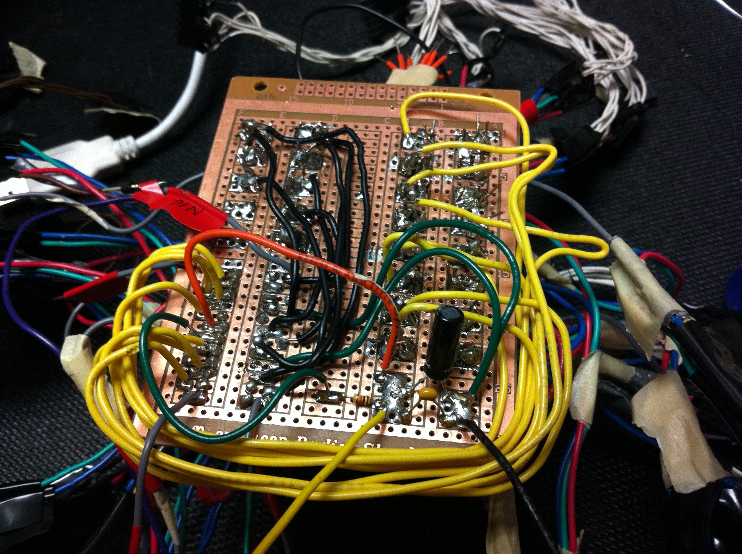
LED matrix solder board
There are three colors of LEDs, and when the touch screen is idle they are programmed to loop between red, green and blue respectively. When the user activates angles in the matrix, the respective segments light up. The center button press is mapped to all red LEDs lighting up. Thus, the touchscreen can demonstrate its operation if the user has no access to a computer.
Software
The program is structured based on the state machine to capture data from the camera. As the camera was the most intensive portion of the circuit, all computations had to be accommodated with the time given in-between pixel samples. We used the camera capture state machine designed by the 3D Scanner group, and worked from that point to incorporate the computations and features required by our touch screen device.
Microcontroller Code
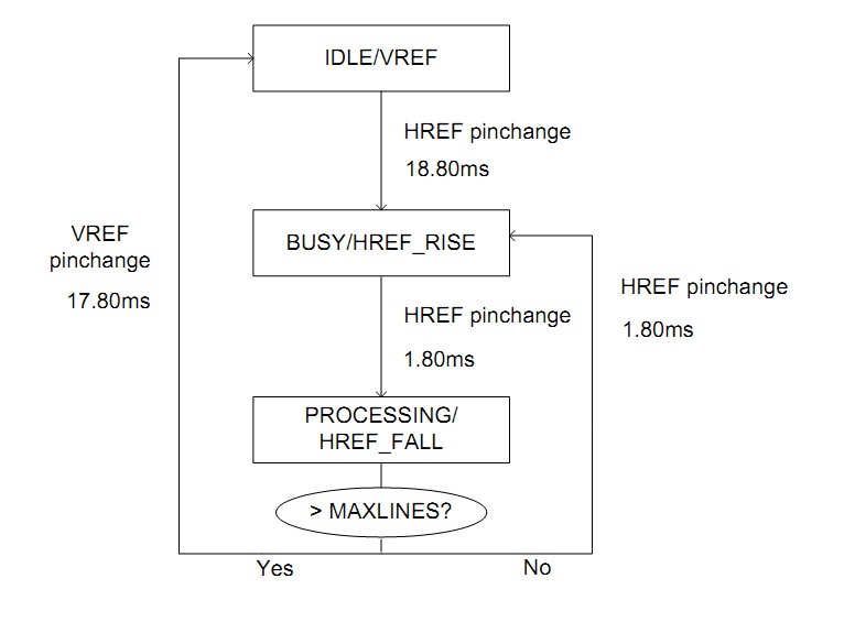
Main State Machine
The program first initializes by programming the camera with the required register settings and by initializing the LED driver. After this is completed, the interrupt ISR routine begins. A change in VREF is first determined. After it has been detected, the interrupt pin change is set to monitor HREF. On every subsequent change of the HREF signal, the program begins to collect data, and subsequently process and communicate it over serial.
After slowing down the HREF and PCLK signals by four times, we obtained the following timing specifications: HREF has positive width 2.0ms, PCLK 3.5micros. In addition, there is a gap of about 19ms in between successive frames.
IDLE/VREF
Processes the current image data to determine the angles which have been activated by the user, and sends the information via serial.
BUSY/HREF_RISE
Collects new pixel information, and stores them in the appropriate data arrays.
PROCESSING/HREF_FALL
Sends the line of pixel data collected over serial.
State Machine
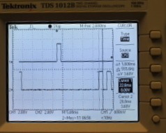
Timing of VSYNC with HREF signals at start/end of a frame
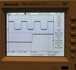
HREF and PCLK timing
Data Capture
Image data contains intensity information on a scale of 16 to 240. The minimum and maximum intensity values encountered so far in the current frame is tracked, but the intensity values for all other pixels are discarded. Instead, the result of a thresholding function is stored in a set of arrays encoding an image of size 30x30 pixels. The threshold is recomputed after every frame to be a value halfway between the minimum and maximum intensity, at least 100 in value, and given a difference of at least 20 between the minimum and maximum intensities. The value changes dynamically with the lighting conditions, allowing us to resolve blobs well and to exclude noise from the environment.
Data Processing
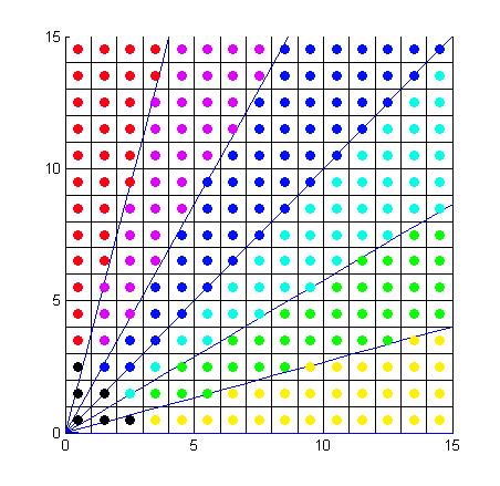
Pixel ownership to angles within a quarter of the image screen
Using the image data, the program computes for every angle its updated state (activated/not activated). We chose 6 angles in every quarter as it offers a good balance between our image resolution and the size of the FTIR blob detected. If the sum of the cells within a certain angle is above a threshold value, the angle is activated. For every angle, its member cells can only exist in a quarter of the image array. Using this structure, we can divide the array into four data structures, used to access and store data.
Data Transmission
We experimented with several types of data encodings over UART. At the pixel clock speed of 1.214MHz, the camera is outputting frames at about 6 fps. Thus, the width of each HREF signal is about 2.0ms. Since we only have about 18ms between each VREF signal, there is insufficient time to transmit about 30 lines of data over serial. Instead, the line sending is completed at the next HREF tick, when no data collection is occurring.
10XXXXXXXX
Reduced encoding format
Our initial idea was to transmit 8 bits of data over the serial, but realized that for all datasets beginning with 00, a control character would be issued instead. In addition, there is limited support for the extended ASCII character set, for characters starting with 10 or 11. Thus we encoded 6 bits of data in every byte transmitted. This enabled us to transmit the entire line of data in just under 1ms.
MessageExample string for 12 bits of dataExample string efficiencyEfficiency for data line of 30 bitsPerformance (ms)Naive binary approach 111000010000 0.125 0.1210 10.00
Hex Encoding E100 0.375 0.4167 4.65
Reduced Encoding xP 0.75 0.6250 0.939
Communication Code
Camera Communication
The camera has an onboard ADC, converting a pixel-by-pixel scan of the image into a stream of bits. However, the camera's normal resolution of 356x292 pixels and 30fps speed was too fast for the Atmega644 interrupt routine to sample. We chose to slow down the pixel clock by four times using a counter, reducing the resolution of the image down to a 30x30 pixel array. In addition, this method gives us a few hundreds of cycles of processor time that is not spent entering and exiting the interrupt service routine. We chose the QCIF format, which reduces the image to 176x144, and further programmed the windows to yield 120x120. From this array, sampling every fourth horizontal reference signal and every fourth pixel yielded our 30x30 image. We originally were working with a 60x60 image, and found that the image took up too much memory due to the 4kB limit. Our decision was then to apply a threshold filter and store only the result of the filter, a binary array of foreground and background pixels.
LED Driver Communication
The SPI interface is straightforward to implement. The processor maps the angles that are activated to a sequence of LED lights to light up. Every time the processor enters into idle mode, the LEDs are driven to the new state.
MATLAB Front-End Code
Angle Processing Code
To generate the logical checks for the angle activations, we wrote a program that will generate the checking code for any image size and any number of angles. This allows us to scale up and down the angle sensitivity of the device. We have determined that 6 angle segments per sector is a good value.
Single Image Code
This code captures a single, full resolution image from the sensor. This was helpful in debugging the image received from the camera and verifying the FTIR effect.
Serial Input/Mouse, Keyboard Output Code
MATLAB supports basic serial port communication. The program repeatedly polls the serial port for new image data. When the end frame symbol is found, the program processes the received image following the appropriate decoding and outputs it on a figure.
We have developed two small applications that use the image stream as an input to the computer. These inputs utilize the java.awt.Robot package, that allows for simulation of user input events.
Using the angle data array, we can apply the circular correlation function to determine the most likely motion that occurred. This computed speed is then translated into a keyboard press. We configured a free DJ software, Virtual DJ, to associate these keys with appropriate turntable rotations.
The user can start or pause a song loaded on the deck by tapping the center of the screen, and then begin scratching by drawing lines or making rotational motions on the surface.
Results
Our device receives 396 frames per minute, or about 6.5 frames a second over the UART connection. If the camera image is disabled, the camera can be sped up to receive about 8.5 frames per second. This allows for smoother control of the wheel. Even at 6.5 fps, the device is responsive enough for basic deejaying control. However, this assumes that the user has been able to supply good blobs on the acrylic surface.
The touch screen sensitivity is a function of the user's fingers. We found that dry skin does not frustrate light on the screen easily. In this instance, hard pressure produces minimal blobs. Applying some oil or moisture to fingertips greatly improves the sensitivity, to the extent that even resting lightly on the surface will generate blobs on the screen. In addition, it is physically difficult to scratch at high speeds across the acrylic surface, due to friction.
Since the light only generates light and outputs signals via the serial port connection, it is unlikely that our device would interfere with nearby devices in harmful ways. Naturally, light sensitive applications will have their accuracy impacted, but the device will not cause damage to their circuitry.
The device operates well in indoor lighting. This is a result of the filter used. However, shining infrared light directly into the interface will interfere with the operation of the touch screen. If the recommended voltage of 9V is used to power the microcontroller board, the infrared LEDs do not heat up and the device can be used continuously.
Our device does not contain any parts that could harm the user. The infrared light generated is directed into the surface of the acrylic, and only a small amount escapes as a result of FTIR. In addition, the light is diffused and not directed. The LED display does not flicker visibly at rates which could trigger epileptic episodes.
The device is not limited to finger tips. Any material with the appropriate index of refractivity will generate the FTIR effect on our screen. However, due to the auditory and visual nature of the entertainment device, users who are hearing and vision impaired will not be able to use the full functionality of the DJTouch.
Please refer to the additional videos below for a demonstration of the device's performance.
Tiffany gives an introduction to the DJ Touch (video courtesy of Bruce Land)
Mouse Application
We ask a guest DJ to perform (video courtesy of Bruce Land)
Conclusion
We have met our initial expectations in the project, having developed a touchscreen that is able to work as a virtual turntable in a potential deejaying setup. In particular, we were able to use the touchscreen as a mouse input to the computer.
The lack of a compliant surface in our touchscreen makes it difficult for users to use the device, without the application of oil/water as required. We would consider applying a thin surface of silicon to the device, which would allow for light touches to be registered as blobs on the screen.
In addition, we would have considered the option of a high speed connection to the computer in order to boost the rate of data transfer. As this was one of the bottlenecks in the timing for our program, we could potentially speed up the device even further, increasing the frame rate and sensitivity of the device.
Standards
We communicate to the camera using I2C. The camera is specific to the device, but any other camera that is programmable via I2C could replace it. The device also drives the LED matrix using the SPI protocol. However, we do not read in from the device, so it is not fully implemented.
Intellectual Property
Hardware Design
Our touchscreen utilizes the method discovered and popularized by Jeff Han. In addition, we made use of the installation guides by the NUIGroup and Thomas Brand to guide us through the process. The LED Matrix control of the 60 LEDs followed the schematic on the Arduino playground community pages. The build of the LED infinity tunnel is inspired by several youtube videos. VirtualDJ Home is a free software for non-commercial use. As DJTouch is intended solely for educational purposes, this fits the criteria.
Software Design
We used libraries from Peter Fleury's I2CMaster implementing the I2C protocol. In addition, we relied on the state machine design from the Scanalicious project, written by Ryan Dunn and Dale Taylor.
We designed and wrote all other portions of code. SPI code was written based on the datasheet information on the Atmega644 and the MAX7219, and the serial port data encoding was implemented ourselves.
Legal Considerations
We have included videos of our device playing songs on the Virtual DJ software. The software links up with internet music streaming services, granting user access to a large library of songs. Users who are unregistered are permitted to play a 30-second sample of songs from this library. These songs are protected by copyright laws and unfair use of the material is a criminal act. However, under the Fair Use Act, material can be used under certain conditions without penalty. We believe that our use of the song samples to demonstrate our device falls under this category; we intend for the DJ Touch to be an educational device and do not intend to market or sell it, and the demonstration is purely to show the functionality of our device and does not serve as a means of commercial advertising or contain any political agendas.
Ethical Considerations
During the course of the project, we have adhered closely to the IEEE code of ethics.
Our device is primarily an entertainment device, and built to demonstrate proof of a low-cost FTIR device operating on minimal processing power. We have designed it such that does not pose any danger or harm to users, as it is a static device with a stable build.
We have ensured that the device does not output dangerous levels of infrared radiation, by constructing a device which does not expose the user to direct infrared light. In addition, we have reported truthfully on the performance of our device. Our data is obtained by oscilloscope readings, and we have given all information that is required for a similar device to be constructed.
As our device is not intended for sale, we do not have any perceived conflicts of interest. Instead, the device is a demonstration of a concept, and we believe the DJ Touch will inspire future work.
Through our report, we have detailed the problems and solutions in the course of getting the touch screen operational. By publishing the information publicly, others will be able to learn from our mistakes or find useful solutions to their problems.
When in contact with vendors, we stated the educational aims of our project and were honest about our association with Cornell University.
Appendices
Program Listings
DJ Touch Builds
The compressed folder contains both the MATLAB serial port code as well as the code for the microprocessor.
Streaming Camera Feed DJTouch
Fast Rotation-Only DJTouch
Additional Useful Functions
Single Image Capture
Angle Processing Code
Schematic
Link
Cost Details
PARTCOSTSOURCETotal $73.60 --C3038 Camera $30.00 Electronics123
Atmega644 $8.00 lab
Prototype board $8.00 lab
Infrared LEDs (12, at $0.3 unit cost) $3.60 eBay
Bulk LEDs (60, at $0.05 unit cost $3.00 eBay
Solder board 6 inch (2, at $2.50 unit cost) $5.00 lab
Small solder board $1.00 lab
9V Power Supply $5.00 lab
16 MHz Crystal Oscillator -- lab
various resistors, capacitors -- lab
MAX7219 (sampled) MAXIM
CD4516BE $0.00 lab
1" 6"x6" acrylic $10.00 jmkdisplays
Two-way mirror (overstock piece) $4.00 Two Way Mirrors
Mirror $0.00 (owned)
790nm filter (on loan) Prof Pollock
Scrap wood, metal $0.00 --
Task Breakdown
Tiffany
Construction
Touchscreen
Report
Kritarth
LED Matrix
LED control code
Serial processing on computer
References
Datasheets
OV6330
C3038 Camera
MAX7219 LED Driver
Atmega644
CD4510B
Vendor Websites
JMK Display
Two Way Mirrors
Maxim
Software Design sources
Virtual DJ
Peter Fleury's I2C library
Camera Capture state machine adapted from Scanalicious
GUI automation using a Robot in MATLAB
SPI code taken from Atmega644 datasheet.
Hardware Design sources
Thomas M. Brand's guide to FTIR. Essential for getting our device to work.
NUI Group's Wiki on FTIR Technology
LED Infinity Tunnel implementation
Arduino LED Matrix
Acknowledgements
We would like to thank Prof. Bruce Land for providing us the knowledge and resources to complete this project. Without his support and guidance this project would not have been possible. We would also like to extend our thanks to the Teaching Assistants of ECE 4760 Spring 2011, especially our section TA Rohan Sharma (M.Eng).
The project would not have been possible without the infrared filter kindly lent to us by Professor Pollock, and we also thank him for his assistance with shaping the mirror for the infinity tunnel.
Finally, we would like to thank the Intel Robotic Competition team for allowing us the use of their lab and tools.


No comments:
Post a Comment